Showing posts with label module 3 Electrical Fundamentals. Show all posts

Thursday, July 15, 2021

SUBTOPICS OF MODULE 3

Module 3 will be into 18 subsection following the system in part 66 under EASA. The topics will as follows:

1. Electron Theory
2. Static Electricity and Conduction
3. Electrical Terminology
4. Generation of Electricity
5. DC sources of electricity
6. DC Circuits
7. Resistance and Resistor
8. Power
9. Capacitance and capacitor
10. Magnetism
11. Inductance and Inductor
12. DC Motor/ Generator Theory
13. AC Theory
14. RCL Circuits
15. Transformers
16. Filters
17. AC Generators
18. AC Motors

Wednesday, March 16, 2016

TRANSFORMER

Transformer is included to module 3. The syllabus is as follows...

3.15 Transformers (L2)
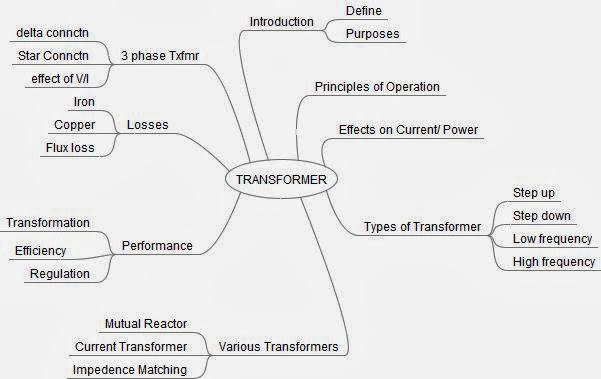
Transformer construction principles and operation;
Transformer losses and methods for overcoming them;
Transformer action under load and no-load conditions;
Power transfer, efficiency, polarity markings;
Calculation of line and phase voltages and currents;
Calculation of power in a three phase system;
Primary and Secondary current, voltage, turns ratio,power, efficiency;
Auto transformers.

I have included a short youtube video, It is noted that the video does not cover the whole syllabus...


I intend to add more contents

Monday, December 22, 2014

DC Generator Overhaul


UNDER  EDITING


Testing The Armature
There are 2 basic test:
- Using meter
- Using Growler

1. Test Using Gowler
Growler is like the primary winding of a transformer. When the armature is positioned on the growler, the armature is acting like the secondary of the transformer. However, please take note that the secondary winding of the armature is open circuit, so no current flows in the armature windings but there are the induced voltage

a. Check for short circuit.


Thursday, February 6, 2014

Transformer Module 3:15

The Part 66 document list the content of the syllabus.

The contents can be summarized as follws:


Monday, December 24, 2012

AC Motors - US Air Force Training Film

I was using this video for the teaching of AC motor. It was produces by the US Airforce in 1969, I have to accept that it is rather an old video, black and white, but it had the main advantage that is was designed for training of the airforce personnel. Some of the new videos are intended for marketing rather than training.


 AC motors are widely used in industry as well as in aircraft. It varies in size from a miniature size to the huge units. There are many different types of AC motors, such synchronous, induction motors or hysteresis motors. The simplest and the most common type of motors is the induction motors. For that reason, the video concentrates on this motor.

A: Construction of Induction Motors.
It consists of three separate parts:
- end bell - at both end of the rotor and it consists of bearing assembly.
- the housing that contain the stator fields
- the rotor.
Because of it simplicity, it is easier to construct and robust.

B. Principle of operation
a. to demonstrate the principle, a simple gadget was designed with represent the rotating magnetic fields and the rotor. The field is spinned by hand and rotor will follow the rotating fields.

b.A model of rotating field and the rotor is shown proving the operation.

c. The production of rotating field - A good simple model was build to physically demonstrate the production of rotating field. Even two phases of 90degrees apart, the rotating field can be produced.

d. The production of electro-magnet in the rotor.
The rotor consists of wire conductors joint at the end by metal conductors. As there are the changing rotating  magnetic field, current will flow in the rotor and produce magnet field.
Note: Requirement for the production of induction: conductor, magnetic field and relative motion.


Saturday, December 1, 2012

Module 3 17 AC Generator

The AC generator module is towards the end of module 3. Among the topics to covered under module 3.17 are:

A. Syllabus
1. The Rotation of loop in a magnetic field and waveform produced;

2. The Operation and construction of revolving armature and revolving field type AC generators;

3. Single phase, two phase and three phase alternators;


4. Three phase star and delta connections advantages and uses;

5. Permanent Magnet Generators

The knowledge level is level 2. That mean, it is expected the students to be able to....
- explain the principles/ theory and fundamental and the components or elements

- provides the typical examples.
- use the mathematical formulae when explaining and do the calculation.
- The applicant should be able to read and understand sketches, drawings and schematics describing the subject. This include the schematic symbols and wiring diagram
- The application of the  knowledge, where it is used in the aircraft.
          For level 3 include the integration with other systems.


B: Prior Knowledge

To understand the operation of an AC Generator, these prior knowledge are required.
- Faradays Law,
- Lenzs Law
- Flemings R/H rule
- Vector diagram, adding and subtracting vectors.
- angular velocity


VIDEO 3.17


Thursday, November 8, 2012

Induction Motor - How it works

Induction motor is commonly used in the aircraft. It is robust, simple and can last a long time.

Principle of Operation.
It works on the principle of rotation magnetic field, the stator is connected to the 3 phase power supply, and the rotor consist of a caged aluminium bars. Current is induced in the rotor which flows in the cage to form electromagnet. The rotor will follow the rotation of the stators field.


Rotating magnets formed by 3 pairs of stator windings connected to the 3 phase AC power.


The 3 phase supply offers the natural 3 phase rotation field.


Construction
Take note of the 2 major parts of the induction motor, the rotor and the stator. The stator is fitted with 3 pairs of windings, correspond to the the phases, A,B and C. The rotor consists of copper bars joined at both ends.


The Operation
When the star windings are connected to the 3 phase supply, the winding A and A1 will form North and South poles. You can imagine the north pole start at winding A, than it moves to pole B and next to the pole C.


Youtube Video
 

Sunday, October 21, 2012

Module 3.16 Filters

Filters is cover under the syllabus in module 3.16 at level 1 It covers operation, application and uses of 4 types of filters, low pass, high pass, band pass and band stop. A Low pass. The following video explain the
low pass filter.


F(cutoff) = 1/2(pfi)RC

A. About filters - What is a filter.
In the basic science in school, we learn about filter that was used to separate a liquid and the solid impurities. In electronics, the same concept is used. A filter is to separate different signals of different frequencies. The easiest to visualize is in the music, the filters used to divert different signals to different speakers.

B. Filters - EASA syllabus
Under module 3.6, The topic "Filters" is at level 1 and include its Operation, application and uses of the these  filters: low pass, high pass, band pass, band stop.

- Low pass filter - a filter that allows the signal below a certain frequency to pass through unchanged.The point to start the change is the cut-off point.

- High pass filter - a filter that allows the signal above a certain point to pass through unchanged.


Module 3.8 Power

Under the EASA part 66 syllabus, the module 3.8 is about the following topics (level 2):
- Power, work and energy (kinetic and potential
- dissipation of power using resistor
- Power formula
- calculation involving power, work and energy

The Video gives the formula for power in a dc circuit: power = IV = V squared/ R = I squared/ R

Saturday, October 13, 2012

Electrical System Typical B737NGX

Module 4 does not cover a typical electrical system. This would be covered in module 11A, however it make it easier for student to appreciate what they have learned if a typical aircraft system is given.

I have selected a video by angle of attack, giving a brief overview on the Boeing 737NGX electrical system.
The video is designed for the pilot.It is good for introduction, as it does not go into detail as required for the engineers.

Friday, October 12, 2012

Syllabus Module 3 - Electrical Fundamental


After Mathematics and Physics in modules 1 and 2, the next appropriate module is module 3.

I include the syllabus from Malaysian DCA, which is similar to the EASA syllabus.

3.1 Electron Theory B1 - Level 1,
Structure and distribution of electrical charges within: atoms, molecules, ions, compounds; Molecular structure of conductors, semiconductors and insulators.

3.2 Static Electricity and Conduction (B1 L2)
Static electricity and distribution of electrostatic charges;
Electrostatic laws of attraction and repulsion;
Units of charge, Coulomb's Law; Conduction of electricity in solids, liquids, gases and a vacuum.

3.3 Electrical Terminology (B1-L1)
The following terms, their units and factors affecting them: potential difference, electromotive force, voltage, current, resistance, conductance, charge, conventional current flow, electron flow.

3.4 Generation of Electricity (B1-L1)
Production of electricity by the following methods: light, heat, friction, pressure, chemical action, magnetism and motion.

3.5 DC Sources of Electricity (B1-L2)
Construction and basic chemical action of: primary cells, secondary cells, lead acid cells, nickel cadmium cells, other alkaline cells;
Cells connected in series and parallel;
Internal resistance and its effect on a battery;
Construction, materials and operation of thermocouples;
Operation of photo-cells.

3.6 DC Circuits (B1-L2)
Ohms Law, Kirchoff's Voltage and Current Laws;
Calculations using the above laws to find resistance, voltage & current;
Significance of the internal resistance of a supply.

3.7 Resistance/Resistor (L2)
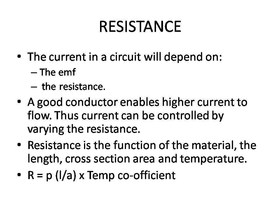
(a) Resistance and affecting factors; Specific resistance;
Resistor colour code, values and tolerances, preferred values, wattage ratings;
Resistors in series and parallel;
Calculation of total resistance using series, parallel and series parallel combinations;
Operation and use of potentiometers and rheostats;
Operation of Wheatstone Bridge.

(b) Positive and negative temperature coefficient conductance; (L1)
Fixed resistors, stability, tolerance and limitations, methods of construction;
Variable resistors, thermistors, voltage dependent resistors;
Construction of potentiometers and rheostats;
Construction of Wheatstone Bridge;

3.8 Power (L2)
Power, work and energy (kinetic and potential);
Dissipation of power by a resistor;
Power formula;
Calculations involving power, work and energy.

3.9 Capacitance/Capacitor (L2)
Operation and function of a capacitor;
Factors affecting capacitance area of plates, distance between plates, number of plates, dielectric and dielectric constant, working voltage, voltage rating;
Capacitor types, construction and function;
Capacitor colour coding;
Calculations of capacitance and voltage in series and parallel circuits;
Exponential charge and discharge of a capacitor, time constants;
Testing of capacitors.

3.10 Magnetism (B2)
(a) Theory of magnetism;
Properties of a magnet;
Action of a magnet suspended in the Earth's magnetic field;
Magnetisation and demagnetisation;
Magnetic shielding;
Various types of magnetic material;
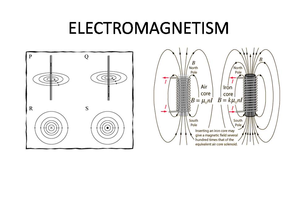
Electromagnets construction and principles of operation;
Hand clasp rules to determine: magnetic field around current carrying conductor.

(b) Magnetomotive force, field strength, magnetic flux density, permeability, hysteresis loop, retentivity, coercive force reluctance, saturation point, eddy currents;
Precautions for care and storage of magnets.

3.11 Inductance/Inductor (L2)
Faraday's Law;
Action of inducing a voltage in a conductor moving in a magnetic field;
Induction principles;
Effects of the following on the magnitude of an induced voltage: magnetic field strength, rate of change of flux, number of conductor turns;
Mutual induction;
The effect the rate of change of primary current and mutual inductance has on induced voltage;
Factors affecting mutual inductance: number of turns in coil, physical size of coil, permeability of coil, position of coils with respect to each other;
Lenz's Law and polarity determining rules;
Back emf, self induction;
Saturation point;
Principle uses of inductors;

3.12 DC Motor/Generator Theory (L2)
Basic motor and generator theory;
Construction and purpose of components in DC generator;
Operation of, and factors affecting output and direction of current flow in DC generators;
Operation of, and factors affecting output power, torque, speed and direction of rotation of DC motors;
Series wound, shunt wound and compound motors;
Starter Generator construction.

3.13 AC Theory (L2)
Sinusoidal waveform: phase, period, frequency, cycle;
Instantaneous, average, root mean square, peak, peak to peak current values & calculations of these values, in relation to voltage, current & power;
Triangular/Square waves;
Single/3 phase principles.

3.14 Resistive (R), Capacitive (C) and Inductive (L) Circuits (L2)
circuits, parallel, series and series parallel;
Power dissipation in L, C and R circuits;
Impedance, phase angle, power factor and current calculations;
True power, apparent power and reactive power calculations.

3.15 Transformers (L2)
Transformer construction principles and operation;
Transformer losses and methods for overcoming them;
Transformer action under load and no-load conditions;
Power transfer, efficiency, polarity markings;
Calculation of line and phase voltages and currents;
Calculation of power in a three phase system;
Primary and Secondary current, voltage, turns ratio,power, efficiency;
Auto transformers.

3.16 Filters (L1)1
Operation, application and uses of the following filters: low pass, high pass, band pass, band stop.

3.17 AC Generators (L2)
Rotation of loop in a magnetic field and waveform produced;
Operation and construction of revolving armature and revolving field type AC generators;
Single phase, two phase and three phase alternators;
Three phase star and delta connections advantages and uses;
Permanent Magnet Generators.

3.18 AC Motors (L2)2
Construction, principles of operation and characteristics of: AC synchronous and induction motors both single and polyphase;
Methods of speed control and direction of rotation;
Methods of producing a rotating field: capacitor, inductor, shaded or split pole.

Monday, August 6, 2012

Module 3 Electrical Resources - Category B1


Syllabussyllabus
Questions
3.1Electron Theory Level 11
3.2
2. Static Electricity and Conduction
3
3. Electrical Terminology
4
4. Generation of Electricity
5
5. DC sources of electricity
6
6. DC Circuits
7
7. Resistance and Resistor
8
8. Power
9
9. Capacitance and capacitor
1. Introduction: Youtube Video
10
10. Magnetism
part66school.blogspot.my/2015/11
11
11. Inductance and Inductor
12
12. DC Motor/ Generator Theory
1-DC Generator and Motor Video
13
13. AC Theory
14Resistive (R), Capacitive (C) and Inductive (L) Circuits L2Individual RCL circuits
15
15. Transformers
1. Generic Video
16
16. Filters
1. Filter -Introduction
17AC Generators1.My Video
18AC Motors1. Video US Airforce
2. Blog entry 25 Dec 2014

Slides Resources1.Basic Electric 1-1 week
2. Basic Electric 2 - 1 week
Other Resources1. Introduction to small aircraft electric
2. B737NGX elect system overview 

Test/ Assessment           Formative Questions   |  Assessment 1       | Assessment 2

Sunday, August 5, 2012

Individual RCL in AC Circuits

Let us review the characteristics of current against the voltage if were to connect a resistance and an inductance across aa AC power supply.

The connections are given below. Please view the RC circuit (resistant and inductance)
Resistance/ Inductance / and Capacitive Curcuits 
A. Resistive Circuit.
This exists in theory only, a circuit will always have inductance and capacitance value.
As the voltage is applied directly on the resistor, and it a known variable, it is taken as the reference. Then we need to know the characteristics of the current, is it in phase with the voltage?
As there is no inductance and capacitance, the current will be directly proportional to the applied voltage and it is exactly in phase.
The following points are to be noted:
- The value of the voltage and current is always quoted in RMS value.
- To draw a graph, the instantaneous current value is given by the formula  I=V/R


Module 3 Basic Electric Part 1 of 2


Ohm's law is the basic for studying the effect of current and voltage. Given the resistance and temperature remaining constant, the value of current is proportional to the voltage.

I = V/R  and  V= IR
......................................................


In an aircraft, the circuit does not operate independently. It can be connected to the earth.
The following are the method to be used in handling the issue of the potential different with respect to the earth.

1. Find the total resistance. It is given by the formula, Rt = R1+ R2 +R3
2. Find the current flowing in the circuit, I = V/Rt
3. With the current known, the voltage drop for each resistor can be calculate.
4. If the earth point is identified as above, the potential at each point with respect to the earth can be easily identified.

----------------------------------------------------------