This an introductory video. I would start with explaining what it is.
PLEASE READ THE TEXT AND THEN WATCH THE VIDEO.
A. Operational Amplifier is a analogue circuit, with a set of input and an output. It is a very flexible amplifier and by changing the external wiring, it can be used for different functions.
It uses include
- mathematical functions of adding and subtraction multification.
- Amplifiers - DC amplifier and AC
- comparator
- Summation
B. Characteristics
- High gain
- Input impedance - very high and does not load the source
- Output impedance - zero
- Bandwidth - indefinite
- Supply voltage - unaffected by the load
C. Example
- Gain 200,000 voltage gain
- Input impedance - 2Mohm
- output impedance - 75 ohms
- Bandwidth - to 1 MHz
- Supply Voltage .... + and - 5 to 15 volts
D. Notation
The Operation amplifier can be shown as a 5 pin IC,
Thyristors are a family of semi conductor devices sharing a common characteristic.. they will latch to the last position. if its conducting or On, it remain ON until the current drops below the threshold level.
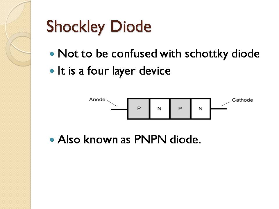
The syllabus mentions about the SCR, the oldest generation of thyristors. We will cover other types such as DIAC and Trics. In ths short session we will look at the characteristic, the construction and the operation. We will startt with the oldest, which is the Shockley diode. As this diode allows current to flow one way only, two shockley diodes are combined to form a diac, which allow current to flow both ways.
Then we look at the characteristic of the DIAC
Opto-thyristors has the same characteristics like the earlier mentioned items. but with one different, it operated by light like the photodiodes. The students need to remember the basic characteristic of semiconductor, the resistance decreases as the temperature increases. The resistance reduce as it receive more light. When resistance reduces, current increase
Module 4 is about the basic electronics. Under this topic we are learning about the semi-conductors and its components and integrated circuits.
Prior Knowledge
Before you can discuss how a diode work, you have to have a basic understanding of semiconductor, the atomic structure and the way the current flows.
Introduction.
After the doping process, basically there are 2 type of semiconductor, the P-type and the N-type. P type, has shortage of electrons, the doping process has introduced material with only 3 valence electron. Thus its major current carrier is "holes".
The N-type of material has excess electrons. This is because the doping material had 5 valence electrons.
How Diode Works
A diode will allow current to flow with lesser resistance if it is connected following the arrow as in the schematic symbol. Although we normally say that the reversed flow is blocked, in reality, there is always the breakdown point. The resistance will break above a certain voltage.
Microprocessor is a relatively new invention. As the name implies, the processor is made of micro-components integrated into one unit. Prior to this, each of the component is made separated and later integrated in a printed circuit board.
The first microprocessor was C4004 built in 1969 for the Nippon Calculating Machine. Intel was engaged for the the project. The creator of 4004 later left Intel and started another company known as AMD. The 8-bit processor was later developed and enhance. The well known version was the 8088, which was used in the early IBM PCs.
AMD started as the contracted producer of Intel microprocessors. That time the microprocessors were relatively slow, the speed was about 5-10 mhz and the components count was about 29,000.
16 bit processor - was introduced in 1982 as the 80186 processor. The speed was between 3-20 Mhz and able to process about 2.5 million processes per second. Then the 80286 was released. AMD continued to produce a clone of Intel.
32 bit processor was introduced in 1989 as i860. i960 was later introduced in the same year. The speed had reach 100Mhz and processing ability was about 5 MIPS. The x86 version was the first to reach 1million components per processor. Pentium was introduced in 1993.
The latest Intel Processor in 2012, the i7, is operating at 3.5GHz, with 8MB cache.
Having the basic understanding of a microprocessor and the its various elements is necessary. It is not only for your EASA licensing examination, but for your later working knowledge as aircraft nowadays are fitted with modern black boxes containing the microprocessors.
This post is about multimeter. From its name, you can expect that the meter it to measure a number of functions. The most common are:
- AC Voltage
- DC Voltage
- DC Current
- Resistances
There are a number of skills set you need to have to use the meter effectively. There are:
- meter construction theory
- basic electric circuit theory.
- safety practices
- practical skills.
A: Meter construction theory. You can still be able to use the meter effectively even if you do not have any theoritical background knowledge. However you will have a number of disadvantages, for example, you are likely unable to know if the meter is in good operating condition or not.
Basically all meters, in its basic form are ammeters. That means it is operated by current. The way the circuits are wired will determine if it is voltmeter, ammeter or ohmmeter.
B: The basic circuit theory: It is required to assist you in deciding on how to connect the meter. To read the voltage, you have to choose two points to measure the potential different. Thus the voltmeter connection is in parallel. To read current, the meter has to be connect in series with the load.
To read the resistance, the resistor has to be isolated, otherwise the reading will not be accurate.
C: Safety practices: Current can cause death and injury. This mean, you have to know how to work with electricity. Unless you know for certain, assume that the wire or connections have fatal voltage. A voltage as low as 50 volt can cause injury. Avoid wearing conductive rings or watches, as these items can be in contact with life wire.
D: Practical Skills will enable you to handle the equipment and wiring.


