Reading through the documents from Airbus can be difficult if you do not know the short forms and abbreviations used. My personal experience require me to pause and search for the meaning of the abbreviations, as such I and collecting the data and put it in this blog.
ADCN - Analogue/Digital Converter
ADDA - Analogue/ Digital Digital Analogue
AFDX - Aircraft Full Duplex
AIMS - Aircraft Information and Management System
API - Application programming interface
ARINC 664 is the standard for deterministic ethernet network used in avionics databus for A380 and B787.
COTS - Commercial Off the Shelf.
CPIOM - Core Processor and Input/ Output Module
GWM - Gate Way Module
IMA - integrated modular avionics
Incremental qualification - each system manufacturer has to integrate his own functions without concern with the others. ( Refer aslo partitioning)
LRU - Line Replaceable Unit
PDM - Product Data Management
PSM - power supply unit
RDC - Remote Data Concentrator
VL - Vertical Link
I an putting the relevant reference that I manage to pick into this blog to assist those sitting for EASA category B1.1 examination.
Friday, December 28, 2012
Thursday, December 27, 2012
Aviation Law and Regulation
Understanding the law and regulation is part of the syllabus to become a licensed engineer. I have included a video giving the historical perspective of the aviation laws.
The first international conference on Civil Aviation was held in Paris in 1919 where one of the item agreed was the authority of the country on its air space. As the number of aircraft and the international flights increased, the main concerns were on the safety and the international co operations between nations. The worlds had witnessed a fast development of aircraft during the second world war. When the war ended, there was high number of idle aircraft that were made available for commercial usage.
In 1944, USA took the lead and invited the nations for a conference in Chicago.This had led to the creation of an international body to regulate the international aviation. Among the agenda of the discussion and the subsequent agreements were:
- the sovereignty of the individual state.
- the exchange of the commercial rights leading to the developments of the documents "Freedom of the Air".
- Tariff and custom rights of the contracting states. The foreign aircraft has to land at the first port of landing at a "custom airport" where the immigration formality are carried out. With the European Union, the requirements are removed.
- The rules on taxation - There is no tax for fuel and oils and technical parts used on the aircraft.
- Marking and registration of aircraft - aircraft have to carry the national markings and the registration marking. Even how the markings to be displayed were agreed.
- Aircraft has to carry a list of documents - they are.. the certificate of airworthiness, crew licenses, load sheet, certificate of registration, radio license and aircraft log book.
The aviation law and regulations are enforced by the individual contracting states based on the agreed terms of the ICAO. There were a number of subsequent conferences that changes some of the terms and references.
Wednesday, December 26, 2012
IMA Integrated Modular Avionics for Licensed Personnel
With the changes in the Easa Part 66 and 147, the three new technology modules are added. They are ATA 42, 45 and 46. In preparing for the modules, I am doing secondary research through the internet and later, to be enrolled in a course. One possible training provider is the Club 66.
1. OBJECTIVE
The purpose of the project is to prepare myself for the module ATA 42 - Integrated modular avionics
2. LITERATURE REVIEW.
a. Definition
Quoted (Philippa)..Integrated Modular Avionics (IMA) is a blanket term used to describe a distributed real-time computer network aboard an aircraft. This network should consist of a number of computing modules capable of supporting numerous applications of differing safety criticality levels.
Wiki (http://en.wikipedia.org/wiki/Integrated_modular_avionics ) defined it as ...Integrated modular avionics (IMA) represent real-time computer network airborne systems. This network consists of a number of computing modules capable of supporting numerous applications of differing criticality levels.
b. Historical Perspective
In the early 1980s, the avionics started to replace the mechanical functions in the commercial aircraft. (Henning Butz 20xx). In early 1990s, the classical concept of "1 function = 1 computer" can no longer be maintained, due to the increasing number of demands for the computers. Then the designers came out with concept of multiple software with different criticality level operated within a single processor. It did solve the weight and number of computers, but it had lead to the "transparent fault propagation", which affect the reliability and the maintenance cost.
In 1995, Honeywell introduced the concept of "IMA" on B777, featuring...
- modularized cabinet packaging with
- "time triggered back plane data communication" and
- "application progam interface" API
- strong "SW/SW" partitioning
- HW/SW segregation
- precise fault monitoring
The IMA had proven to meet the reliability and the required performance.
The development on A380, focused on the open system.
The followings are the features.
- maintain the segregation features and the API services
- the proprietary cabinets and backplane solution were replaced.
- Introduced CPIOM (core processor-input output module) usinf ARINC 600 standard box.
- Aircraft Full Duplex (AFDX) of 100Mbit connecting the CPIOM.
REFERENCES
- Philippa at http://www-users.cs.york.ac.uk/~philippa/IMA.html on 26 Dec 2012
- Wiki at http://en.wikipedia.org/wiki/Integrated_modular_avionics on 26 Dec 2012
Monday, December 24, 2012
AC Motors - US Air Force Training Film
I was using this video for the teaching of AC motor. It was produces by the US Airforce in 1969, I have to accept that it is rather an old video, black and white, but it had the main advantage that is was designed for training of the airforce personnel. Some of the new videos are intended for marketing rather than training.
AC motors are widely used in industry as well as in aircraft. It varies in size from a miniature size to the huge units. There are many different types of AC motors, such synchronous, induction motors or hysteresis motors. The simplest and the most common type of motors is the induction motors. For that reason, the video concentrates on this motor.
A: Construction of Induction Motors.
It consists of three separate parts:
- end bell - at both end of the rotor and it consists of bearing assembly.
- the housing that contain the stator fields
- the rotor.
Because of it simplicity, it is easier to construct and robust.
B. Principle of operation
a. to demonstrate the principle, a simple gadget was designed with represent the rotating magnetic fields and the rotor. The field is spinned by hand and rotor will follow the rotating fields.
b.A model of rotating field and the rotor is shown proving the operation.
c. The production of rotating field - A good simple model was build to physically demonstrate the production of rotating field. Even two phases of 90degrees apart, the rotating field can be produced.
d. The production of electro-magnet in the rotor.
The rotor consists of wire conductors joint at the end by metal conductors. As there are the changing rotating magnetic field, current will flow in the rotor and produce magnet field.
Note: Requirement for the production of induction: conductor, magnetic field and relative motion.
Thursday, December 20, 2012
Malaysia e-Examination
I was reading with interest that the Malaysia Civil Aviation will be conducting e-examination for Category A, B1 and B2. The present manual examination will end in Dec 2012 and the registration for the e-examination will be opened in Jan 2013.
The applicants for manual examinations for 2013 will be cancelled and all applicants will have to reapply online. This reapplication is necessary as the new system will be fully online and all applicants will have to create their own profile in the DCA data base.
 The applicants will be able to do the followings:
1. create a user account.
2. View the schedules/ sessions
3. Apply for the exam.
4.Pay for the exam.
5. Print the exam slip
6. Sit for the exam at the center.
7. View the result and print the result and the Knowledge deficiency report.
8. Update the personal data.
I am looking forwards to using the facilities for my students, but the am hoping the original plan of examination centers would still be implemented to facilitate development of local capability.
The applicants for manual examinations for 2013 will be cancelled and all applicants will have to reapply online. This reapplication is necessary as the new system will be fully online and all applicants will have to create their own profile in the DCA data base.
1. create a user account.
2. View the schedules/ sessions
3. Apply for the exam.
4.Pay for the exam.
5. Print the exam slip
6. Sit for the exam at the center.
7. View the result and print the result and the Knowledge deficiency report.
8. Update the personal data.
I am looking forwards to using the facilities for my students, but the am hoping the original plan of examination centers would still be implemented to facilitate development of local capability.
Friday, December 14, 2012
Fly By Wire - Introduction
The utilization of the concept fly by wire had been widely used in the military aircraft. The use in civil aircraft has started to gain popularity.

When we mention "fly by wire", it would mean that the pilot is controlling the aircraft through the wire connections. To explain this concept, we need to understand how the aircraft were controlled before "fly by wire" technology was used.
1. The Changing Methods to move the Flight Control.

a. Direct Mechanical link control column to the control surfaces- The earlier aircraft were small.The forces acting on the flight control surfaces, like ailerons, elevator and rudder was small too.So the pilot can manually move the surface through a mechanical connection. The control surfaces were mechanically connected through bell cranks, levers, pulleys and mechanical cables to the control column or steering wheels.
b. Assisted Control
The aileron is controlled by the tab. The movement of the control column to left or right, through mechanical linkages and cable, moves the control tab. The aileron will move in the opposite direction to the tab.
c. Powered Control
Typical example from B737
Take note that the control column transmit the signal to aileron power control unit through a mechanical linkages.

d. Fly by wire (by electrical signal)

2. Factors Leading to Why Fly By Wire.
a. There are a number of reasons why the shift from the mechanical control to the electrical control. With the advance in the technology, majority of the aircraft systems are operated using digital technology. The technology is now available to support the fly by wire and it meets the requirement of the safety and redundancy.
b. The second factor is the sheer size of the aircraft, making the mechanical linkages and cable to complex and heavy. Any additional weight will be an additional cost to the fuel bill.
3. Advantages of Fly by wire system.
a. There is an overall reduction in weight, the lesser the airframe weight, the bigger will be the payload.
b. It makes the Integration of several federated systems into a single system easier.
c. It provide a superior handling. In fact the handling characteristics can be modified and controlled. This had the added advantages in the pilots training.
d. ease of maintenance, the rigging is much simplifies. The troubleshooting is more focused on the LRUs and BITE checks.
This conclude the introduction of fly by wire. The next postings will focus on the systems installed on A320 and Boeing 777.

When we mention "fly by wire", it would mean that the pilot is controlling the aircraft through the wire connections. To explain this concept, we need to understand how the aircraft were controlled before "fly by wire" technology was used.
1. The Changing Methods to move the Flight Control.

a. Direct Mechanical link control column to the control surfaces- The earlier aircraft were small.The forces acting on the flight control surfaces, like ailerons, elevator and rudder was small too.So the pilot can manually move the surface through a mechanical connection. The control surfaces were mechanically connected through bell cranks, levers, pulleys and mechanical cables to the control column or steering wheels.
b. Assisted Control
 |
| Images from FAA AMT manual- |
c. Powered Control
Typical example from B737
Take note that the control column transmit the signal to aileron power control unit through a mechanical linkages.

d. Fly by wire (by electrical signal)

2. Factors Leading to Why Fly By Wire.
a. There are a number of reasons why the shift from the mechanical control to the electrical control. With the advance in the technology, majority of the aircraft systems are operated using digital technology. The technology is now available to support the fly by wire and it meets the requirement of the safety and redundancy.
b. The second factor is the sheer size of the aircraft, making the mechanical linkages and cable to complex and heavy. Any additional weight will be an additional cost to the fuel bill.
3. Advantages of Fly by wire system.
a. There is an overall reduction in weight, the lesser the airframe weight, the bigger will be the payload.
b. It makes the Integration of several federated systems into a single system easier.
c. It provide a superior handling. In fact the handling characteristics can be modified and controlled. This had the added advantages in the pilots training.
d. ease of maintenance, the rigging is much simplifies. The troubleshooting is more focused on the LRUs and BITE checks.
This conclude the introduction of fly by wire. The next postings will focus on the systems installed on A320 and Boeing 777.
Saturday, December 1, 2012
Module 3 17 AC Generator
The AC generator module is towards the end of module 3. Among the topics to covered under module 3.17 are:
A. Syllabus
1. The Rotation of loop in a magnetic field and waveform produced;
2. The Operation and construction of revolving armature and revolving field type AC generators;
3. Single phase, two phase and three phase alternators;
4. Three phase star and delta connections advantages and uses;
5. Permanent Magnet Generators
The knowledge level is level 2. That mean, it is expected the students to be able to....
- explain the principles/ theory and fundamental and the components or elements
- provides the typical examples.
- use the mathematical formulae when explaining and do the calculation.
- The applicant should be able to read and understand sketches, drawings and schematics describing the subject. This include the schematic symbols and wiring diagram
- The application of the knowledge, where it is used in the aircraft.
For level 3 include the integration with other systems.
B: Prior Knowledge
To understand the operation of an AC Generator, these prior knowledge are required.
- Faradays Law,
- Lenzs Law
- Flemings R/H rule
- Vector diagram, adding and subtracting vectors.
- angular velocity
VIDEO 3.17
Thursday, November 29, 2012
Filters under Module 3.16
Filter is under module 3 16 and the level of knowledge is only at level 1. At level 1 the students are expected to describe the subject using common words and examples. Students are also expected to have the knowledge of the common terms related to the subject.
The stated syllabus are as follows... Operation, application and uses of the following filters: low pass, high pass, band pass, band stop.
A. Introduction
If we relate the word filter to the mechanical application, like the water filter, it function include the removal of unwanted particles or impurities. Depending of the type of filter used, it can prevent small or larger particles to pass through.
In we apply the concept to the electronic application, then filters will have the following characteristics.....
- high pass - allows high frequencies to pass through
- low pass - allows low frequency to pass through
- band pass - allows norrow band of frequencies to pass through
- band stop - stop the flow of narrow band of frequencies.
Saturday, November 24, 2012
Module 12.8 Overview
Module 12 is about the real aircraft. The sub-module 8 is about the electrical system.
It must be made clear that under EASA part 66, there is no separate license for Electrical, unlike that of BCAR section L. For that reason, the B1 licensed persons have to develop the competencies in electrical systems. The expected knowledge level is level 3.
The following is the syllabus...
Batteries Installation and Operation;
DC power generation, AC power generation;
Emergency power generation;
Voltage regulation, Circuit protection.
Power distribution;
Inverters, transformers, rectifiers;
External/Ground power
1. The batteries
In module 3, you had done the basic of the batteries and cells. That mean the students should have knowledge on the various aspects of it, such as the chemical reactions, the active materials involved in the reactions of the batteries, its constructions and the maintenance practices.
In this module, it is discussing about the installation.
- I would give the students a simple electrical systems for an aircraft, including..
- the aircraft with DC as the main system,
- aircraft with AC as the main system
Then, the students need to know where the batteries fit in.
The operation will include the batteries uses in normal situation and in emergency situation.
The installation will include the physical installation, the protection against corrosive effects and the guard against overheat. The operation also include the check for serviceability. How would you know if the battery is serviceable or not?.
TO BE ADDED >>>
Friday, November 23, 2012
How to Use Oscilloscope
The knowledge on oscilloscope is not included in the syllabus for B1-1. In fact the word oscilloscope is not even mentioned in the syllabus. However, this information is added for those interested to further their knowledge as oscilloscope may be used for works related to transistors and amplifiers in module 4. We can use it also in our investigation of the properties of AC circuits in module 3.
I find it easy to do research and start to learn on my own with the easy access to the internet. I normally start the research by using the video, the reason is simple, video captures the 2 important senses, the sound and sight. It is easier to understand and to follow the tuition.
I included a video that teaches the use of the unit from the conceptual introduction.
Take note of the following basic adjustments..
- vertical position knob -adjustment for each channel - what it does is, it repositions the output to the visible range of display. This is done without changing the scale of the display.
- horizontal position knob (for all channel) - it moves the images horizontally so that it is visible.
- voltage scale - it changes the volts per division. The adjustment is available for each channel.
- time base - seconds per division. (all channel)
- trigger position.- to adjust so that the wave is stabilized.
Thursday, November 22, 2012
Differences in the Modules Between B1.1 and B1.3
If you are planning to become an aircraft mechanic or engineer, you have some choice to make.
First - Decide whether to become mechanical or avionics. Mechanical is the core, as it deals with the structure and the airworthiness of the aircraft. The hanger check and the related certifications are signed by mechanical or B1 personnel. That does not mean that the avionics is not important, as modern aircraft are fitted with advance systems.
If you want to do avionics, then go for B2 license. For mechanical, you have a choice of separate and related licenses.
These are the choice...
B1-1 - fixed wings with turbine engine - like the modern aircraft B737, B747 A380 etc. Fixed wing because the wings that are producing the lift are fixed and note rotating.
B1 - 3 - This the license for rotary wing. The rotating blades on top of the helicopter are shaped like the wing on aeroplane. The main different, the wings on helicopter rotates.
There are two more choices, the pistons airplane or helicopter. However, they are outside the scope of today's discussion.
Let us contrast the module contents of the two choice (Between B1-1 and B1-3).
a. The modules 1 to 10 are common for both.
b. For those going for B1-1 has to do 3 more modules i.e 11A, 15 and 17
c. For those going for B1-3 has to do modules 12 and 15.
Notes.. module 11A is about fixed wing structure and systems.
12 is about rotorcraft structure and systems.
15 is module on turbine engine
17 is propeller.
Main Differences between module 12 and 11A.
.... to be inserted...
Tuesday, November 13, 2012
Getting to Know Helicopter
In preparation for the teaching of module 12 on Electrical subjects, I have to build up some knowledge of helicopter. I will be doing three ATA chapters, 24, 26 and 33. For the purpose of delivery, I will be conducting the topics on electrical power, Lightings and Fire Protection.
As the students will be the Malaysian Trainees, I will have to select the examples from Malaysian operators.
My first search is for Malaysian Helicopter operators ... Google revealed the following operators..
1. MHS - Malaysia Helicopter Services
2. Eurocopter Malaysia
3. Solaire Helicopter Training
4. Augusta Westland.
Then, my next task is to get the types of helicopter operated by the various companies. The following are the result Helicopters operated the of different companies...

A. MHS
- Europter AS 365 N2
- Eurocopter AS332 L2 Super Puma
- Eurocopter AS335 F2
- Sikosky S76C
B Eurocopter Malaysia
- Dauphin AS365 N1
- Ecureuil AS350 BA
C. Augusta Westland Malaysia
- AW119
- AW109
- AW139
To support the teaching, I need to select 2 models as the reference for teaching. Looking from models above, the most suitable helicopter to be used for reference are the Augusta and Eurocopter.-
Module 12.15 External Light for General Reading
I had been searching the internet for suitable resources to introduce module 12.15 Lighting system. I found a youtube video, but unfortunately, it was uploaded by a person who is not from the industry. However the pictures and videos are useful resources.
The external lights are...
- Navigation Light - left wing tip - red, right wing tip - green, viewed from rear lights- white.
- Beacon Light - rotating or flashing red light - one on top of the aircraft and the other at the bottom.
- Strobe Light - while flashing lights at three locations, wing tips, and tail of the aircraft.
- Landing Light - used on landing and take-off, normally at three locations, wings and center.
- Taxi Light - for the pilots to see the taxiway
- runway turn off - useful for turning
- wing lights - illuminate the wings areas for ground safety and checking for the ice.
- logo light. - commercial value for advertisement.
External lights are used for different purposes. Some are legal requirements, others are operation while some are commercial. These are the uses..
1. Aircraft parked at the bay - the navigation lights are on, logo lights and wing light on.
2. Time limiting lights - The landing lights and taxi lights are high power. When the aircraft is inflight, the air help to cool the lights. For maintenance, switch it on for as short a time as possible.
3. Disturbing the eyes - both the strobe lights and beacons are affecting the eyes. Use the beacon light as necessary to show movements of aircraft or engine is running. Strobe lights to be used when the aircraft is moving in poor visibility.
OVERHEAD PANEL
The control of the external lights are from overhead panel as shown below. (B767)

VIDEO - Caution about the comments.
Monday, November 12, 2012
Module 12 Syllabus for B1.1
Module 12 is the final module for non-engine subject. It is about the aircraft's aerodynamics, structure and systems. That mean, the students are expected to have completed Modules 1 to 10.
Module 11 is divided to two groups, 11A if you are doing Category B1-1 and module 11B for category B1.2, which are airplane with turbine engine and pistons respectively.
If you are going for rotocraft license, either turbine or piston engine, then, you will take Module 12.
If you are a student, it may be worth thinking of taking more than 1 module. The different between modules 11A and 11B, and even module 12 are rather small. So it will save your study time if you can take more than 1 of the quoted modules.
The syllabus for module 12 is given below...
12.1 Theory of Flight — Rotary Wing Aerodynamics Level 2
Terminology; Effects of gyroscopic precession; Torque reaction and directional control; Dissymmetry of lift, Blade tip stall; Translating tendency and its correction; Coriolis effect and compensation; Vortex ring state, power settling, overpitching; Auto-rotation; Ground effect.
12.2 Flight Control Systems Level 3
Cyclic control; Collective control; Swashplate; Yaw control: Anti-Torque Control, Tail rotor, bleed air;
Main Rotor Head: Design and Operation features; Blade Dampers: Function and construction; Rotor Blades: Main and tail rotor blade construction and attachment; Trim control, fixed and adjustable stabilisers; System operation: manual, hydraulic, electrical and fly-by-wire; Artificial feel; Balancing and Rigging.
12.3 Blade Tracking and Vibration Analysis Level 3
Rotor alignment; Main and tail rotor tracking; Static and dynamic balancing; Vibration types, vibration eduction methods; Ground resonance.
12.4 Transmissions (Level 3)
Gear boxes, main and tail rotors; Clutches, free wheel units and rotor brake. Tail rotor drive shafts, flexible couplings, bearings, vibration dampers and bearing hangers.
12.5 Airframe Structures (Level 2)
(a) Airworthiness requirements for structural strength; Structural classification, primary, secondary and tertiary; Fail safe, safe life, damage tolerance concepts; Zonal and station identification systems; Stress, strain, bending, compression, shear, torsion, tension, hoop stress, fatigue; Drains and ventilation provisions;
System installation provisions; Lightning strike protection provision.
(b) Construction methods of: stressed skin fuselage, formers, stringers, longerons, bulkheads, frames, doublers, struts, ties, beams, floor structures, reinforcement, methods of skinning and anti-corrosive protection. Pylon, stabiliser and undercarriage.
12.6 Air Conditioning (ATA 21)
12.6.1 Air supply (L2)
Sources of air supply including engine bleed and ground cart;
12.6.2 Air Conditioning (L3)
Air conditioning systems;Distribution systems; Flow and temperature control systems; Protection and warning devices.
12.7 Instruments/Avionic Systems
12.7.1 Instrument Systems (ATA 31) (L2)
Pitot static system:altimeter, air speed indicator, vertical speed indicator; Gyroscopic:artificial horizon, attitude director, direction indicator, horizontal situation indicator, turn and slip indicator, turn coordinator; Compasses: direct reading, remote reading; Vibration indicating systems — HUMS; Glass Cockpit; Other aircraft system indication.
12.7.2 Avionic Systems (L1)
Fundamentals of system layouts and operation of:
Auto Flight (ATA 22); Communications (ATA 23); Navigation Systems (ATA 34).
12.8 Electrical Power (ATA 24) (L3)
Batteries Installation and Operation; DC power generation, AC power generation; Emergency power generation; Voltage regulation, Circuit protection. Power distribution; Inverters, transformers, rectifiers; External/Ground power.
12.9 Equipment and Furnishings (ATA 25) (L2)
(a) Emergency equipment requirements; Seats, harnesses and belts; Lifting systems.-
(b) Emergency flotation systems; (L1)
Cabin lay-out, cargo retention; Equipment lay-out; Cabin Furnishing Installation.
12.10 Fire Protection (ATA 26) (L3)
Fire and smoke detection and warning systems; Fire extinguishing systems; System tests.
12.11 Fuel Systems (ATA 28) (L3)-
System lay-out; Fuel tanks; Supply systems; Dumping, venting and draining; Cross-feed and transfer; Indications and warnings; Refuelling and defuelling.
12.12 Hydraulic Power (ATA 29) (L3)
System lay-out; Hydraulic fluids; Hydraulic reservoirs and accumulators; Pressure generation: electric, mechanical, pneumatic; Emergency pressure generation; Pressure Control; Power distribution; Indication and warning systems; Interface with other systems. Filters.
12.13 Ice and Rain Protection (ATA 30) (L3)
Ice formation, classification and detection; Anti-icing and de-icing systems: electrical, hot air and chemical;
Rain repellant and removal; Probe and drain heating. Wiper system.
12.14 Landing Gear (ATA 32) (L3)
Construction, shock absorbing; Extension and retraction systems: normal and emergency; Indications and warning; Wheels, tyres, brakes; Steering; Skids, floats. Air ground sensing.
12.15 Lights (ATA 33) (L3)
External: navigation, landing, taxiing, ice; Internal: cabin, cockpit, cargo; Emergency.
12.16 Pneumatic/Vacuum (ATA 36) (L3)
System lay-out; Sources: engine, compressors, reservoirs, ground supply; Pressure control; Distribution; Indications and warnings; Interfaces with other systems.
12.17 Integrated Modular Avionics (ATA42) (L2)-
Functions that may be typically integrated in the Integrated Modular Avionic (IMA) modules are, among others:
- Bleed Management, Air Pressure Control, Air Ventilation and Control, Avionics and Cockpit Ventilation Control, Temperature Control, Air Traffic Communication, Avionics Communication Router, Electrical Load Management, Circuit Breaker Monitoring, Electrical System BITE, Fuel Management, Braking Control, Steering Control, Landing Gear Extension and Retraction, Tyre Pressure Indication, Oleo Pressure Indication, Brake Temperature Monitoring, etc Core System; Network Components.
12.18 On Board Maintenance Systems (ATA45) (L2)
Central Maintenance Computers; Data loading systems; Electronic library system; Printing; Structure monitoring (damage tolerance monitoring)
12.19 Information Systems (ATA46) (L2)
The units and components which furnish a means of storing, updating and retrieving digital information traditionally provide on paper, microfilm or microfiche. Includes units that are dedicated to the information storage and retrieval function such as the electronic library mass storage and controller. Does not include units or components installed for other uses and shared with other systems, such as flight deck printer or general use display
Typical example include Air Traffic and Information Management System and Network Server Systems
Aircraft General Information Systems;
Flight Deck Information System;
Maintenance Information System;
Passenger Cabin Information System;
Miscellaneous Information System;
How Helicopter Flies
Although my focus is on avionics and electrical systems, I do need to have some knowledge on other systems. As one of the module covered in the blog is EASA part 66 module 12, which is about rotorcraft systems, some knowledge of helicopter aerodynamics is necessary.
For my shared learning, I enclose a video on how helicopter flies.
The concept of directional control
There are only two set control surfaces that dictate the flying direction of the helicopter.
- The main rotor
- the tail rotor.
By changing the effective forces of the main rotors, determines the direction of the helicopter.

1. The speed of the rotor
2. the angle of attack
3. the gyroscopic effect
4. the differential forces between the blades.
If both of the rotor provide equal force, then the helicopter will just move vertically up. This is done by the collective control lever.

Let say the lift is more at 3 o'clock. It appear that the helicopter would lean to the left and bank to the left. But gyroscope property will shift the lift by 90 degrees, thus the helicopter will pitch down.
Sunday, November 11, 2012
Module 12 Avionics Topics
As this blog is focusing on electrical and avionics, I have to decide which topics are included. To the students, this is not an issue as they have to do the whole topics of module 12.
A. Electrical Topics -(Level 3) To be taught by instructors with Electrical License under Section L
a. Module 12.8 -Electrical Power (ATA 24 level 3)
- Batteries installation and operation
- DC Power Generation
- AC Power Generation, voltage regulation
- Ground Power
- Emergency Power, Invertor, rectifier
- Power Distribution, transformer,
b. Module 12.10 - Fire Protection (ATA 26) - Include topics on the detection of fire and smoke, Fire extinguishing system and System Test.
c. Module 12. 15 - Lights (ATA33) External Light - Navigation, Landing, taxi and Ice, Beacon
Internal - Cabin, cockpit and cargo.
Emergency - Doors and Floor
B. Instruments and Avionics System
a. Module 12.7.1 Instrument System (level 2)
b. Module 12.7.2 Avionic Systems (level 1)
C. Latest Avionic Sysems
a. Module 12.17 - Integrated Modular Avionics (ATA 42 Level 2)
b. Module 12.18 - On Board Maintenance Sysem (ATA 45 level 2)
c. Module 12.19 - Information System (ATA 46 level 2)
Thursday, November 8, 2012
Induction Motor - How it works
Induction motor is commonly used in the aircraft. It is robust, simple and can last a long time.
Principle of Operation.
It works on the principle of rotation magnetic field, the stator is connected to the 3 phase power supply, and the rotor consist of a caged aluminium bars. Current is induced in the rotor which flows in the cage to form electromagnet. The rotor will follow the rotation of the stators field.

Rotating magnets formed by 3 pairs of stator windings connected to the 3 phase AC power.

The 3 phase supply offers the natural 3 phase rotation field.
Construction
The Operation
When the star windings are connected to the 3 phase supply, the winding A and A1 will form North and South poles. You can imagine the north pole start at winding A, than it moves to pole B and next to the pole C.
Youtube Video
Principle of Operation.
It works on the principle of rotation magnetic field, the stator is connected to the 3 phase power supply, and the rotor consist of a caged aluminium bars. Current is induced in the rotor which flows in the cage to form electromagnet. The rotor will follow the rotation of the stators field.
Rotating magnets formed by 3 pairs of stator windings connected to the 3 phase AC power.
The 3 phase supply offers the natural 3 phase rotation field.
Construction
 |
| Take note of the 2 major parts of the induction motor, the rotor and the stator. The stator is fitted with 3 pairs of windings, correspond to the the phases, A,B and C. The rotor consists of copper bars joined at both ends. |
The Operation
When the star windings are connected to the 3 phase supply, the winding A and A1 will form North and South poles. You can imagine the north pole start at winding A, than it moves to pole B and next to the pole C.
Youtube Video
Wednesday, October 31, 2012
Software Management Module 5:13
 |
Software Management - The title consists of two words, software and management. The software can be defined as the program that are used by a computer. We can basically divided software into 2 groups, operating software and application software. Operating software focus on making the computer and its accessories work. The application software is the program designed to produce the specific job for the user.
Management control is the process planning and other activities to ensure that the software meets the desired results. There more to the application of management, but I always stress on the management of the process, which relate to the software life-cycle. |
 |
| Software Management is under the subtopic 13 in the Module 5 for the EASA part 66 license. Module 5 is about Digital Technique and electronic instruments. In teaching this module, I expect the students to be able to explain and give examples to show their understanding of the modules title. It |

 |
| Software in a necessary components of an aircraft system. Examples of aircraft systems using software are...primary and secondary flight controls, engines controls, electrical generation and distribution, brakes and navigation systems. |
 |
| Let us take a look at the life cycle of a software. The like of human life cycle, the software has the different phases of life. The authority is interest to monitor and control the quality of the different phases. |
 |
| The RTCA and Eurocae are responsible to come up with guidelines to ensure the the software used on the aircraft meets the required specification. The specification was published in the joint documents, DO -178/ED - 2. The current version of the documents are given in another slides. The Malaysian Civil Aviation recognized the document through its airworthiness directive AN57. |
 |
| The document gives the outline for approval of software. The designed of the software must be done by an approved company. The requirements are described by RTCA and Eurocae. |
 |
| About RTCA |


 |
| Software Testing |

====================================================

 |
| The example of data loading panel is taken from B737-400 manual. This will give the students some idea of where the loading process is being done. There is the |
 |
| On the loading is done through the optical disk. This must be clear to the students that the software to be local must be an approved software and the workers that is doing the loading must be an approved person. |
Monday, October 29, 2012
Syllabus Module 5
Module 5 is about Digital Techniques and Electronic Instruments. The followings are the syllabus for module extracted from the EASA part 66 module (Malaysia)
5.1 Electronic Instrument Systems
Typical systems arrangements & cockpit layout of electronic instrument systems.
5.2 Numbering Systems Numbering systems:
binary, octal and hexadecimal; Demonstration of conversions between the decimal and binary, octal and hexadecimal systems and vice versa.
5.3 Data Conversion Analogue Data, Digital Data;
Operation and application of analogue to digital, and digital to analogue converters, inputs and outputs, limitations of various types.
5.4 Data Buses
Operation of data buses in aircraft systems, including knowledge of ARINC and other specifications; Aircraft network / Ethernet.
5.5 Logic Circuits
(a) Identification of common logic gate symbols, tables and equivalent circuits; Applications used for aircraft systems, schematic diagrams. (b) Interpretation of logic diagrams.
5.6 Basic Computer Structure (a) Computer terminology (including bit, byte, software, hardware, CPU, IC, & various memory devices such as RAM, ROM, PROM); Computer technology (as applied in aircraft systems). (b) Computer related terminology; Operation, layout and interface of the major components in a micro computer including their associated bus systems; Information contained in single and multiaddress instruction words; Memory associated terms; Operation of typical memory devices; Operation, advantages and disadvantages of the various data storage systems.
5.10 Fibre Optics Advantages and disadvantages of fibre optic data transmission over electrical wire propagation; Fibre optic data bus; Fibre optic related terms; Terminations; Couplers, control terminals, remote terminals; Application of fibre optics in aircraft systems.
5.11 Electronic Displays Principles of operation of common types of displays used in modern aircraft, including Cathode Ray Tubes, Light Emitting Diodes & Liquid Crystal Display.
5.12 Electrostatic Sensitive Devices Special handling of components sensitive to electrostatic discharges; Awareness of risks and possible damage, component and personnel anti-static protection devices.
5.13 Software Management Control Awareness of restrictions, airworthiness requirements and possible catastrophic effects of unapproved changes to software programmes.
5.14 Electromagnetic Environment Influence of the following phenomena on maintenance practices for electronic system: EMC-Electromagnetic Compatibility EMI-Electromagnetic Interference HIRF-High Intensity Radiated Field Lightning/lightning protection
5.15 Typical Electronic/Digital Aircraft Systems General arrangement of typical electronic/digital aircraft systems and associated BITE (Built In Test Equipment) testing such as:
ACARS-ARINC Communication & Addressing and Reporting System
ECAM-Electronic Centralised Aircraft Monitoring
EFIS-Electronic Flight Instrument System
EICAS-Engine Indication and Crew Alerting System
FBW-Fly by Wire FMS-Flight Management System
GPS-Global Positioning System IRS-Inertial Reference System
TCAS-Traffic Alert Collision Avoidance System Integrated Modular Avionics Cabin Systems Information Systems
---------------------------------------------------
QUESTIONS FOR EASA PART 66 EXAMINATION
Subject Module 5 Digital Techniques/Electronic Instrument Systems:
Category A-16 multi-choice and 0 essay questions. Time allowed 20 minutes.
Category B1.1 & B1.3-40 multi-choice and 0 essay questions. Time allowed 50 minutes.
Category B1.2 & B1.4-20 multi-choice and 0 essay questions. Time allowed 25 minutes.
Category B2-70 multi-choice and 0 essay questions.
Time allowed 90 minutes.
How Computer Adds Numbers
One one the subject a student learns for the EASA part66 examination is working of a computer.
This is a good video with plenty of information. These are the key points you can pick up...
a. Information on the motherboard and the microprocessor.
b. Basic information of MosFet transistor with source, drain and gate.
c. Understanding the OR and the AND gate.
d. Binary numbers and its representation using the lights.
e. The different type of dates, OR, AND and Exclusive OR.
f. The full and half adder.
Saturday, October 27, 2012
Monday, October 22, 2012
Reading Analogue Multimeter
Reading the analogue multimeter is a necessary skill for aircraft engineer. Unfortunately the EASA syllabus is arranged in such a way that the learning about multimeter is covered in module 7. However students are expected to be able to use the meter as the earlier modules, such as module 3 and 4 require the use of meter for testings. Example module 3. 9, test of capacitor and module 4. 1, the test for diode.
I had located the site to learn about multimeter. Please follow the link to:
http://www.tequipment.net/pdf/velleman/velleman_avm360_manual.pdf
The area of knowledge to be covered in the use of the meter.
Although it is not stated that the students need to know the working of the meter, I do cover it in order to bring the understanding of the usage of the meter.
a. Construction of the meter.
b. The changes and connections needed to make it reads current, voltage and resistance.
c. The names of the different parts and scales.
d. How to use it to read DC voltage and Current, AC voltage and resistance.
e. The different between Digital and analogue meter.

 Take note: for ampere and voltage readings, 0 is on the left and maximum is on the right. However for resistance (ohms) , 0 is on the right and maximum is on the left. Why?. As a student of aircraft maintenance license, you should be able to explain why.
 There are three connecting terminals. Many students are wondering about output terminal. The purpose is to measure AC Voltage, when the AV voltage is superimposed on DC.

I had located the site to learn about multimeter. Please follow the link to:
http://www.tequipment.net/pdf/velleman/velleman_avm360_manual.pdf
The area of knowledge to be covered in the use of the meter.
Although it is not stated that the students need to know the working of the meter, I do cover it in order to bring the understanding of the usage of the meter.
a. Construction of the meter.
b. The changes and connections needed to make it reads current, voltage and resistance.
c. The names of the different parts and scales.
d. How to use it to read DC voltage and Current, AC voltage and resistance.
e. The different between Digital and analogue meter.


Sunday, October 21, 2012
Module 3.16 Filters
Filters is cover under the syllabus in module 3.16 at level 1
It covers operation, application and uses of 4 types of filters, low pass, high pass, band pass and band stop.
A Low pass.
The following video explain the
low pass filter.
F(cutoff) = 1/2(pfi)RC
A. About filters - What is a filter.
In the basic science in school, we learn about filter that was used to separate a liquid and the solid impurities. In electronics, the same concept is used. A filter is to separate different signals of different frequencies. The easiest to visualize is in the music, the filters used to divert different signals to different speakers.
B. Filters - EASA syllabus
Under module 3.6, The topic "Filters" is at level 1 and include its Operation, application and uses of the these filters: low pass, high pass, band pass, band stop.
- Low pass filter - a filter that allows the signal below a certain frequency to pass through unchanged.The point to start the change is the cut-off point.
- High pass filter - a filter that allows the signal above a certain point to pass through unchanged.
Module 3.8 Power
Under the EASA part 66 syllabus, the module 3.8 is about the following topics (level 2):
- Power, work and energy (kinetic and potential
- dissipation of power using resistor
- Power formula
- calculation involving power, work and energy
The Video gives the formula for power in a dc circuit: power = IV = V squared/ R = I squared/ R
- Power, work and energy (kinetic and potential
- dissipation of power using resistor
- Power formula
- calculation involving power, work and energy
The Video gives the formula for power in a dc circuit: power = IV = V squared/ R = I squared/ R
Friday, October 19, 2012
Wednesday, October 17, 2012
Module 7 Electrical Subjects
If you are going for B1.1 license, there are three big module for you to do. They are:
- module 7 - Maintenance Practices
- module 11A - Aerodynamics, Structure and System
- Module 15 - Turbine engine
To facilitate in the delivery of the lectures, we had divided the module 7 into 4 submodules, one of which is on the electrical subject. It covers the following subjects:
- Topic 7.1 - electrical safety
- Topic 7.4 - General Test Equipment
- Topic 7.5 - Schematic and Wiring Diagram
- Topic 7.7 - EWIS
- Topic 7.15 - Soldering
Saturday, October 13, 2012
Electrical System Typical B737NGX
Module 4 does not cover a typical electrical system. This would be covered in module 11A, however it make it easier for student to appreciate what they have learned if a typical aircraft system is given.
I have selected a video by angle of attack, giving a brief overview on the Boeing 737NGX electrical system.
The video is designed for the pilot.It is good for introduction, as it does not go into detail as required for the engineers.
I have selected a video by angle of attack, giving a brief overview on the Boeing 737NGX electrical system.
The video is designed for the pilot.It is good for introduction, as it does not go into detail as required for the engineers.
Friday, October 12, 2012
Syllabus Module 3 - Electrical Fundamental
After Mathematics and Physics in modules 1 and 2, the next appropriate module is module 3.
I include the syllabus from Malaysian DCA, which is similar to the EASA syllabus.
3.1 Electron Theory B1 - Level 1,
Structure and distribution of electrical charges within: atoms, molecules, ions, compounds; Molecular structure of conductors, semiconductors and insulators.
3.2 Static Electricity and Conduction (B1 L2)
Static electricity and distribution of electrostatic charges;
Electrostatic laws of attraction and repulsion;
Units of charge, Coulomb's Law; Conduction of electricity in solids, liquids, gases and a vacuum.
3.3 Electrical Terminology (B1-L1)
The following terms, their units and factors affecting them: potential difference, electromotive force, voltage, current, resistance, conductance, charge, conventional current flow, electron flow.
3.4 Generation of Electricity (B1-L1)
Production of electricity by the following methods: light, heat, friction, pressure, chemical action, magnetism and motion.
3.5 DC Sources of Electricity (B1-L2)
Construction and basic chemical action of: primary cells, secondary cells, lead acid cells, nickel cadmium cells, other alkaline cells;
Cells connected in series and parallel;
Internal resistance and its effect on a battery;
Construction, materials and operation of thermocouples;
Operation of photo-cells.
3.6 DC Circuits (B1-L2)
Ohms Law, Kirchoff's Voltage and Current Laws;
Calculations using the above laws to find resistance, voltage & current;
Significance of the internal resistance of a supply.
3.7 Resistance/Resistor (L2)
(a) Resistance and affecting factors; Specific resistance;
Resistor colour code, values and tolerances, preferred values, wattage ratings;
Resistors in series and parallel;
Calculation of total resistance using series, parallel and series parallel combinations;
Operation and use of potentiometers and rheostats;
Operation of Wheatstone Bridge.
(b) Positive and negative temperature coefficient conductance; (L1)
Fixed resistors, stability, tolerance and limitations, methods of construction;
Variable resistors, thermistors, voltage dependent resistors;
Construction of potentiometers and rheostats;
Construction of Wheatstone Bridge;
3.8 Power (L2)
Power, work and energy (kinetic and potential);
Dissipation of power by a resistor;
Power formula;
Calculations involving power, work and energy.
3.9 Capacitance/Capacitor (L2)
Operation and function of a capacitor;
Factors affecting capacitance area of plates, distance between plates, number of plates, dielectric and dielectric constant, working voltage, voltage rating;
Capacitor types, construction and function;
Capacitor colour coding;
Calculations of capacitance and voltage in series and parallel circuits;
Exponential charge and discharge of a capacitor, time constants;
Testing of capacitors.
3.10 Magnetism (B2)
(a) Theory of magnetism;
Properties of a magnet;
Action of a magnet suspended in the Earth's magnetic field;
Magnetisation and demagnetisation;
Magnetic shielding;
Various types of magnetic material;
Electromagnets construction and principles of operation;
Hand clasp rules to determine: magnetic field around current carrying conductor.
(b) Magnetomotive force, field strength, magnetic flux density, permeability, hysteresis loop, retentivity, coercive force reluctance, saturation point, eddy currents;
Precautions for care and storage of magnets.
3.11 Inductance/Inductor (L2)
Faraday's Law;
Action of inducing a voltage in a conductor moving in a magnetic field;
Induction principles;
Effects of the following on the magnitude of an induced voltage: magnetic field strength, rate of change of flux, number of conductor turns;
Mutual induction;
The effect the rate of change of primary current and mutual inductance has on induced voltage;
Factors affecting mutual inductance: number of turns in coil, physical size of coil, permeability of coil, position of coils with respect to each other;
Lenz's Law and polarity determining rules;
Back emf, self induction;
Saturation point;
Principle uses of inductors;
3.12 DC Motor/Generator Theory (L2)
Basic motor and generator theory;
Construction and purpose of components in DC generator;
Operation of, and factors affecting output and direction of current flow in DC generators;
Operation of, and factors affecting output power, torque, speed and direction of rotation of DC motors;
Series wound, shunt wound and compound motors;
Starter Generator construction.
3.13 AC Theory (L2)
Sinusoidal waveform: phase, period, frequency, cycle;
Instantaneous, average, root mean square, peak, peak to peak current values & calculations of these values, in relation to voltage, current & power;
Triangular/Square waves;
Single/3 phase principles.
3.14 Resistive (R), Capacitive (C) and Inductive (L) Circuits (L2)
circuits, parallel, series and series parallel;
Power dissipation in L, C and R circuits;
Impedance, phase angle, power factor and current calculations;
True power, apparent power and reactive power calculations.
3.15 Transformers (L2)
Transformer construction principles and operation;
Transformer losses and methods for overcoming them;
Transformer action under load and no-load conditions;
Power transfer, efficiency, polarity markings;
Calculation of line and phase voltages and currents;
Calculation of power in a three phase system;
Primary and Secondary current, voltage, turns ratio,power, efficiency;
Auto transformers.
3.16 Filters (L1)1
Operation, application and uses of the following filters: low pass, high pass, band pass, band stop.
3.17 AC Generators (L2)
Rotation of loop in a magnetic field and waveform produced;
Operation and construction of revolving armature and revolving field type AC generators;
Single phase, two phase and three phase alternators;
Three phase star and delta connections advantages and uses;
Permanent Magnet Generators.
3.18 AC Motors (L2)2
Construction, principles of operation and characteristics of: AC synchronous and induction motors both single and polyphase;
Methods of speed control and direction of rotation;
Methods of producing a rotating field: capacitor, inductor, shaded or split pole.
Thursday, October 11, 2012
Teaching Module 4 - Electronics
The module 4 is for Fundamental Electronics. It has 2 distinct group of knowledge. The syllabus includes:
- subject of electronics and the second part
- includes the non electronic subject of syncro.
I presume that EASA realise the importance of subjects of data transmission like syncro and they cannot find a suitable module.As such it is parked in module 5.
In the learning theory, the researches had identified the effectiveness of the teaching medium.
- virtual
- audio
- experiential
It had been found that experiential learning is more effective. That mean, learning by doing will improve the learning and the students memory. We were using this method in the delivery.
We include some of the students activities..
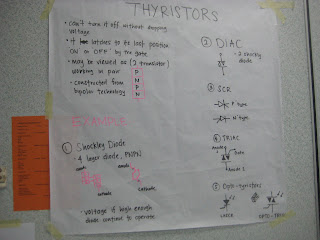 Thrystors are generic term used to describe the semiconductors that have the latching effect. The most commonly used is the SCR, the silicon controlled rectifier. A SCR has 3 connecting wires, the anode, the cathode and the gate.
The + is connected to the anode and (-) connected to the cathode. The gate is the controlling input. With a positive pulse, the current will flow from anode to cathode and it continue to flow until the voltage falls below a certain level.

We covers the half wave and full wave rectifiers. For the full wave rectifier, we study the two types, the center tapped full wave rectifier that uses only two diodes. We also study the bridge type of rectifier which uses 4 diodes.
We did not cover the 3 phase rectifier. That remind me, to include the 3 phase rectifier, as it is the most common type used in the modern aircraft, noticeably for TRUs and the voltage regulators.
 We covered rather in detail about the operation amplifiers. Covering the above topics, we cover the operation of 3 types of Op amplifiers, the inverting, the summing and comparator.


- subject of electronics and the second part
- includes the non electronic subject of syncro.
I presume that EASA realise the importance of subjects of data transmission like syncro and they cannot find a suitable module.As such it is parked in module 5.
In the learning theory, the researches had identified the effectiveness of the teaching medium.
- virtual
- audio
- experiential
It had been found that experiential learning is more effective. That mean, learning by doing will improve the learning and the students memory. We were using this method in the delivery.
We include some of the students activities..

The + is connected to the anode and (-) connected to the cathode. The gate is the controlling input. With a positive pulse, the current will flow from anode to cathode and it continue to flow until the voltage falls below a certain level.

We covers the half wave and full wave rectifiers. For the full wave rectifier, we study the two types, the center tapped full wave rectifier that uses only two diodes. We also study the bridge type of rectifier which uses 4 diodes.
We did not cover the 3 phase rectifier. That remind me, to include the 3 phase rectifier, as it is the most common type used in the modern aircraft, noticeably for TRUs and the voltage regulators.


Saturday, September 29, 2012
Operational Amplifier - Video 1
This an introductory video. I would start with explaining what it is.
PLEASE READ THE TEXT AND THEN WATCH THE VIDEO.
A. Operational Amplifier is a analogue circuit, with a set of input and an output. It is a very flexible amplifier and by changing the external wiring, it can be used for different functions.
It uses include
- mathematical functions of adding and subtraction multification.
- Amplifiers - DC amplifier and AC
- comparator
- Summation
B. Characteristics
- High gain
- Input impedance - very high and does not load the source
- Output impedance - zero
- Bandwidth - indefinite
- Supply voltage - unaffected by the load
C. Example
- Gain 200,000 voltage gain
- Input impedance - 2Mohm
- output impedance - 75 ohms
- Bandwidth - to 1 MHz
- Supply Voltage .... + and - 5 to 15 volts
D. Notation

The Operation amplifier can be shown as a 5 pin IC,
Module 4 Thyristors and SCR
Thyristors are a family of semi conductor devices sharing a common characteristic.. they will latch to the last position. if its conducting or On, it remain ON until the current drops below the threshold level.


RESOURCES
 |
| The syllabus mentions about the SCR, the oldest generation of thyristors. We will cover other types such as DIAC and Trics. In ths short session we will look at the characteristic, the construction and the operation. We will startt with the oldest, which is the Shockley diode. As this diode allows current to flow one way only, two shockley diodes are combined to form a diac, which allow current to flow both ways. Then we look at the characteristic of the DIAC |


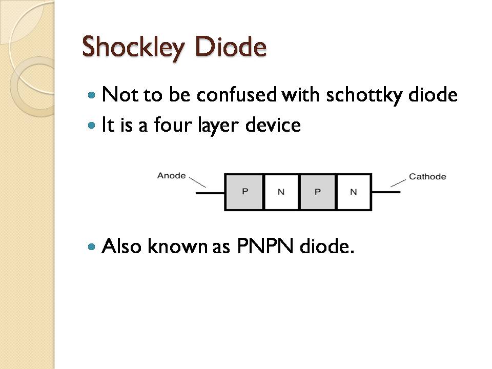


 |
| Opto-thyristors has the same characteristics like the earlier mentioned items. but with one different, it operated by light like the photodiodes. The students need to remember the basic characteristic of semiconductor, the resistance decreases as the temperature increases. The resistance reduce as it receive more light. When resistance reduces, current increase |
Subscribe to:
Posts (Atom)