Friday, August 31, 2012

How GPS Works

On of the topic under Module 5: 15 is about a Typical Aircraft Systems: GPS - Global Position System.

1. Introduction
As the name implies, the GPS is about the position of the aircraft on the globe. Before we go into the detail of its operation, let us view the various navigation systems used at different era in our history.

a. Compass - Based on the natural magnetic fields produced in the earth environment. Compass is used to show the direction of the magnetic north. Some of the issues that we face with the compass are:.. - cannot be used above a certain latitude as the magnetic line of force are getting to become vertical. - The accuracy is affected by local magnetism of magnetic material. - The is errors due to the turn and banking of the aircraft.

b. Radio Navigation The radio navigation relies of the radio signal radiated by radio signals from the navigation stations. - VOR - VHF OnmiDirectional Range - produce 360 degrees signal and the aircraft system is able to choose and select the radial. As the VOR station's location is known from the navigation map, the aircraft may compute its position, using 2 stations or DME inputs.

c. INS - Inertial navigation The position of the aircraft is calculated based on its known origin and movements of the aircraft. The movement of the aircraft is calculated by accelerometers.

 2. Different Satellite Navigation System
Currently, there are 2 global navigation systems.

- GPS - by US military
- Glonass - Russian system A third system by European is under development.Refer http://en.wikipedia.org/wiki/Galileo_(satellite_navigation)

3. How GPS Works
24 Navstar satellites

There are 24 active Navstar satellites orbiting the earth at about 12,000 nautical miles above the earth. They are continuously sending signals on L1 channel on 1575.42 MHz for civilian uses. The signals contain the synchronization code, identification code, position and time codes. With the installed aircraft systems, the distant of the aircraft to the satellite is calculated. With four satellites signal received and analysed, the aircraft will be able to locate its position. Other parameters are derived from the instantaneous position of the aircraft.

The amount of time taken for the signal to reach the aircraft and the location of the satellites enable the onboard computer to calculate its relative position. The distant from a satellite is a sphere at a certain distant from the satellite. With 2 satellites, the possible location is at any point forming a circle, where the two sphere meet. With 3 satellies, the position is fixed. The fourth satellite will recheck and confirm the position.

Friday, August 24, 2012

Syllabus Module 4: Electronic Fundamentals

Module 4 prepares the students/ staff for the electronics of the aircraft systems. Here, the basic of the electronics are covered.

The syllabus is rather selective, for example, for B1 modules, it excludes the materials and the electronics properties. However, we include this subjecs in our teaching, as we found out that, to understand the operation of diodes and transistors, the students need to know the materials.

Subtopics A B1 B2
4.1 Semiconductors
4.1.1 Diodes
(a) Diode symbols; (LevelsA -,B1- 2, B2- 2)
Diode characteristics and properties;
Diodes in series and parallel;
Main characteristics and use of silicon controlled rectifiers (thyristors), light emitting diode, photo conductive diode, varistor, rectifier diodes;
Functional testing of diodes.

(b) Materials, electron configuration, electrical properties; (Levels -, -, B2- 2)
P and N type materials: effects of impurities on conduction, majority and minority characters;
PN junction in a semiconductor, development of a potential across a PN junction in unbiased, forward biased & reverse biased conditions;
Diode parameters: peak inverse voltage, maximum forward current, temperature, frequency, leakage current, power dissipation;
Operation and function of diodes in the following circuits: clippers, clampers, full and half wave rectifiers, bridge rectifiers, voltage doublers and triplers;
Detailed operation and characteristics of the following devices: silicon controlled rectifier (thyristor), light emitting diode, Shottky diode, photo conductive diode, varactor diode, varistor, rectifier diodes, Zener diode.


-


-


2


-


2


2
4. 1.2 Transistors
(a) Transistor symbols;  -  , 1, 2
Component description and orientation;
Transistor characteristics and properties.

(b) Construction and operation of PNP and NPN transistors;  - , -, 2
Base, collector and emitter configurations;
Testing of transistors.
Basic appreciation of other transistor types and their uses.
Application of transistors: classes of amplifier (A, B, C);
Simple circuits including: bias, decoupling, feedback & stabilisation;
Multistage circuit principles: cascades, push-pull, oscillators, multivibrators, flip-flop circuits.

4.1.3 Integrated Circuits  (Levels -, 1, - )
(a) Description and operation of logic circuits and linear circuits/operational amplifiers.

(b) Description and operation of logic circuits and linear circuits;  (Levels -, - , 2 )
Introduction to operation and function of an operational amplifier used as: integrator, differentiator, voltage follower, comparator;
Operation and amplifier stages connecting methods: resistive capacitive, inductive (transformer), inductive resistive (IR), direct;
Advantages and disadvantages of positive and negative feedback.

1


-


1


-


4.2 Printed Circuit Boards   (Levels, - , 1, 2)

Description and use of printed circuit boards.
4.3 Servomechanisms   (Levels -, 1 , - )
(a) Understanding of the following terms: Open and closed loop systems, feedback, follow up, analogue transducers;
Principles of operation and use of the following synchro system components/features: resolvers, differential, control and torque, transformers, inductance and capacitance transmitters.

(b) Understanding of the following terms:  (Levels -, - , 2 )
Open & closed loop, follow up, servomechanism, analogue, transducer, null, damping, feedback, deadband;
Construction operation and use of the following synchro system components: resolvers, differential, control and torque, E and I transformers, inductance transmitters, capacitance transmitters, synchronous transmitters;
Servomechanism defects, reversal of synchro leads, hunting.


About HSI - Horizontal Situation Indicator


It started as a simple compass, giving the heading of the aircraft in relative to the magnetic north. Then with the availability of radio navigation, the radio nav is built into the compass giving the navigation reference such as VOR and ADF.

This short video shows the pilots perspective of the HSI.


Some Points to Note:
1. The pilot quoted the HSI to be the combination of gyro and compass. Some instruments contains the physical gyro within the instruments itself. The gyro provide the short term stability especially during turn and bank. The remote compass signal keeps the direction updated.

2. The radio nav provides the aircraft position reference in relation of a given stations or signal radial. A VOR station will provide the onmi-directional radials picked up by the aircraft radios. The VOR station gives 360 radial corresponding to 360 degrees from the station.

3. Modern aircraft may be fitted with GPS, the Global Position System, where the actual position of the aircraft and its height is known. A simple computer can calculate the speed and the acceleration of the aircraft based on the change of the position.  

CAA Recomended References

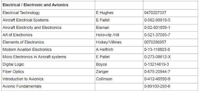
The British CAA had made some recommendations on the study materials to be by the students pursuing the EASA modules.
   

       Titles...................................................................Authors.........................  ISBN
You may search from Amazon Here


The recommendation is made through the CAA documents of ELGD - or Engineer's Licensing Guidance Document.

The are other areas of study discipline included in the original documents. It includes:

- Airframe and Mechanical
- Powerplants

The sections contains list of books recommended for the preparation of the related EASA part 66 modules.

Beside the recommended books, the documents also suggests CAP references (Civil Aviation Publications:

CAP 455 - Airworthiness Notices
CAP 715 - Introduction to Human Factors
CAP 747 - Mandatory Requiements for Airworthiness.

Saturday, August 11, 2012

How ILS System Work

ILS is a standard Instrument Landing System used to guide a landing aircraft. The ILS consist of 4 different radio transmission or subsystems located at the selected locations. They are: 1. The Localiser 2. The Glideslope 3. Compass Locator 4. Marker beacon
To land an aircraft safely, the three axis have to be controlled, the horizontal, vertical and the aircraft speed. That means, the approach angle to the runway must be  right, it had to be at the center of the runway at the suitable speed. The ILS systems provide the signals for the glide angle and the center of the runway.
    
The subsystems are:
a. The localizer:The signal provides the guide to enable the aircraft to follow a straight path towards the center of the runway.It is a expanding signal sent from the end of the runway creating a field of  2.5 degrees ( about 1500 feet wide ate about 5 miles from the runway.

Two sets of transmitter send different frequency signals, 150Mhz on the right and 90Mhz on the left. Both the signal overlap in the middle at the angle of expanding 2.5 degrees. If the aircraft is on the left of the center line, it will receive the 90Mhz signal and the indicator will show that the localizer is on the right.If the aircraft is receiving both, then the system knows that it is on the right path.  
  

b. Glideslope The glideslope provides a path wedge like slope about 3 degrees above the horizon.

The antenna sends a controlled horizontal signals of 2 frequencies, the upper portion is 90Hz and the lower is 150 hz. Both the signal meets to give a center line (chord) of 3 degrees from the end of the runway.
The aircraft is fitted with a antenna, receiver blackbox and indicators.

Indicator: In glass cockpit, the glideslope and localizer are shown on the EADI and EHSI. Sample as below..


C. Marker Beacons


D. Compass Locator
The localizer and glide slope signals cover a very small angle. It is difficult for an aircraft to locate and intercept the signals. A more wide spread signal is required to provide the location where to intercept the ILS. This is provided by the compass locator signal normally situated about 4-7 miles from the runway. It is like a radio station of ADF, where the radio signal is sent 360 signal at 190Hz to 535hz with the range of about 15 miles.

I hope the short article on How ILS system work will give the readers some idea of the system.


Friday, August 10, 2012

Module 5 PFD Landing View


The most important instrument for a flying pilot is the PFD or Primary Flight
display. It was known by different names, it started as artificial horizon, the ADI or attitude director indicator, the FDI indicator and with the lass cockpit, the EADI.

Its functions are:

- attitude reference - it provide the artificial horizon for the pilot to know the aircraft attitude.
- FDI - command bar - provide the command signal, the latter instrument utilize vertical and horizontal bars.
- ILS and Localizer incorporated in the EADI.
- Annunciator Lights -

The modern EADI are either cathode ray tube or LCD.


PFD on Landing

This taken from life aircraft.
Check the PFD, and you will notice the following readings
- altimeter is on the right hand
- Airspeed indicator on the left side.
- The compass reading at the bottom
- The vertical speed on the R/H side

 The glide slope and localizer view is visible only when the signals are captured. The diamond figure indicate the position of the glideslope and localizer in relation to the aircraft. You will notice the rising runway as the aircraft is slowly coming in contact with the runway.

Thursday, August 9, 2012

Formative Assessment

In Training and Education, basically we three groups of assessment, the formative, diagnostic Assessment and Summative Assessment.

I was using the formative and diagnostic assessments. The Summative was given by our exam unit.
---------------------------------------------------------------

Formative Assessment for Basic Electric.

The test would be used to:

a. Adjust the level of contents and identify the weak areas.
b. Prepare the students for the course


1.       The six base SI UNIT that you know are: 1.                                   2.                                            3.                                            4.                                                        5.                                            6

2.       One (I) GIGAbits =                           BITS

3.       Power in electrical circuit  is normally expressed in ………………

4.       The different between atoms and molecules is (are)……………

5.       The 3 fundamental particles of an atom are…
a.       .
b.      .
c.       .

6.       The current in an electrolytes is in the form of …………..

7.       The different between primary and secondary cells is …………………….

8.       An analogue multimeter will be able to measure……1,………          2…………         3………….

9.       Voltmeter  is always connected in…. parallel/series/phase

10.   The OHM’s law is about three elements, they are……….

11.   The value of a resistor is indicated on the resistor by……..

12.   When 2 resistors are connected in parallel, the total resistance is given by………..

13.   Define WORK


14.   An electrical motor convert …………………..  energy to ……………………….. energy


15.   You would define an AC supply by three elements, they are………………


16.   Inductive reactance is like a resistance in an ………….          Circuit

17.   The function of a transformer is…………..

Introduction to small aircraft system

This video was made for pilot training. That make it a introduction to small aircraft system. Pilots need to know the system to the extend that he would be able to operate and identify a normal, abnormal and emergency situation.

It starts with the description of an electrical circuit, with a battery as the power source and a bulb as the load. The animation gives a clearer idea of the concept, where the battery is like a water pump pressurising the pipe, instead of the water, the battery is pressuring the emf, or the electrons.

The series and parallel circuit were introduced. A series circuit provides a single path for the electrons to flow, but a parallel circuit provides at least two separate paths.

 The electrical components.
1. Batteries - A battery stores energy in chemical form. It is mainly used as an emergency source of power. Basically there are two types of batteries used, the nickel cadmium and lead acid. Nickel cadmium is widely used on commercial jets as it last longer, higher capacity and the voltage remains steadier.

2. Alternator - This is also known as a generator. It is driven by the engine's gear box and convert the mechanical energy to electrical energy. To regulate the voltage a voltage regulator is installed. On a small system, it can be part of the alternator.

3. Ammeter and voltmeter. These are the gauge to measure the current and voltage. This is a quality check to make sure that the alternator and battery provide the right voltage and current.  

The distribution
The power has to be distributed


Wednesday, August 8, 2012

Module 3 Basic Electric Part 2 of 2

The diagram shows the AC voltage of a generator. It is in the sinusoidal wave form, pulsing between the positive and negative. It is just like having a water pump that slowly build up pressure in one direction of flow, then it reverse the direction, pumping in the opposite direction.

For the aircraft AC power, the frequency is 400  hertzs at 115 volts.

There are a couples of term with special meaning when it relates to electricity/ There are...
1. peak value
2. peak to peak
3. effective value
4. average value

The above graph is voltage and current against time. Some of the required understanding and definitions are:
a. 1 cycle - it refers to a full electrical cycle, in the graph, from ascending zero value to the next ascending zero.
b. frequency (hertz) the number of cycles per second.
c. peak value - the distant from zero to the highest point in half of the cycle, either positive or negative.
d. peak to peak value - the measure of the highest point for positive to the lowest of negative in one cycle.
e. RMS (root mean square) or effective value - the equivalent DC value that give the same heating effect.
f. average value - the average of the instantaneous value for either the positive or negative portion. If you add both the positive and negative, the value is zero.   
------------------------------------------------------------------------------


7777


.................................................................
The power in AC circuit is slightly different from that in DC circuit. In a DC circuit, the power is given by a simple equation of Power = VI. In AC is gets complex as the current is not always in phase with voltage.

Add caption
Before we go further, we need to review a few definition.
1. Work - work is done when a force cause an object to move in the direction of the applied force. So a force of F acted on an object, and the object was moved by d meters, the amount of work done is given by:
Work (joule) = Force (neutons) x distance (meters)

2. Power is the rate of going work. It is given in joules per seconds or watts. For example, a mass of 1 Kg was moved by 1 meter within 1 second, the power consumed is 1 watt. If the taken is 2 seconds, then the power is 1/2 watt. Please note that the total work done or energy used is the same for work of 1 second or 2 seconds.
In Resistive circuit, the voltage and current are in phase. The power is calculated by voltage x current, as they are in phase, the result, i.e the power is always positive. If we are using the effective value, the RMS, the power is calculated by voltage times current.

It is assumed that the circuit is purely inductive and the current lag the voltage by 90 degrees. In real world there is no such thing as pure reactive load, as all inductance will have some resistance. The diagram below shows the actual power generated in the circuit.


In inductive circuit, the voltage leads the current by 90 degrees. In real circuit, there is no such thing as pure inductance as all inductors will have a built in resistance. Notice that at some point, the result of voltage x current can be negative.  From 0 to 90 degrees, voltage is positive and current is negative,  the resultant power is negative. Theoritically there is no power consumed by the circuit


The above diagram shows the power triangle. The hypotenause is the apparent power given by voltage x current. The horizontal line is VI Cos @, the real power given by the circuit. The reactive power is VI Sine@, a power not realized by the circuit.

The power factor is the value of Cos @. Is is given by the ratio of ,   real power/ apparent power.

........................................................................................................................

Transformer
One of the most common component in an aircraft is the transformers. It basic function is to transform the voltage. The unit which has higher voltage output is called stepped up transformers and those which lower the voltage is known as stepped down transformers. The ratio of output voltage to the input is determined by the turn ratio, that is the ration of windings of the output to the input.

Construction: Transformers are constructor from a soft iron frame with input windings and one or more outputs windings. The soft iron is laminated to reduce the eddy current losses.


The step up transformer: The voltage output is bigger that the input voltage. For this to happen, the secondary winding is more than the primary.
The power input = power out + losses. There is iron loss and copper loss. The iron loss is due the the induced emf on the core, known as eddy current lost. To reduce it, the iron is laminated. Te copper loss is due to the resistance of the winding.

The turn ratio is given by Ts/ Tp

Ts = the number of turn of the secondary winding
Tp = the number of turn of the primary winding.

Not Covered in the presentation
- autotransformer - a transformer with 1 winding and work on the principle of self induction.
- current transformer - a specilized transformer used to measure the current without direct insertion of ammeter.


Monday, August 6, 2012

How To Get Aircraft Maintenance License

EASA is the government body controlling the civil aviation in Europe. Many countries in the world adopted the EASA system. The licensing of aircraft maintenance engineers and mechanics is governed by Part 66 of the EASA document and the control of training school is under part 147.

Malaysia hd adopted the EASA system in January 2010. The Licenses for Malaysian is issued by DCA Malaysia. It is based on UK EASA license as such the licenses is widely recognized and accepted by UK.Many Malaysian find jobs in the middle east, Australia, Europe and Singapore

New Information..
The information on the slides was inserted a few months ago, the latest are as follows..

There were five schools, ATO (Approved Training School) under the previous BCAR Section L Licensing system. The five schools were,  MAS, MIAT, Delog, APR and MATA. When DCAM converted to part 66, the schools had about 6 months to convert to the new rulings. Currently 3 schools are approved under part 147. They are MAS, Dilog and APR.

MAS is conducting training for its own apprentices, Dilog is doing it for FELDA, leaving APR to handle the private students. MIAT is refocusing to be a private Education School under the Ministry of Education and MATA is starting a collaboration to start the Vocational School.

It is advised that the potential students to check the School approval from the authority to avoid future problems. There are many colleges claiming to conduct courses following EASA syllabus. This is misleading as the school can follow the syllabus but they may not be approved.

Module 3 Electrical Resources - Category B1


Syllabussyllabus
Questions
3.1Electron Theory Level 11
3.2
2. Static Electricity and Conduction
3
3. Electrical Terminology
4
4. Generation of Electricity
5
5. DC sources of electricity
6
6. DC Circuits
7
7. Resistance and Resistor
8
8. Power
9
9. Capacitance and capacitor
1. Introduction: Youtube Video
10
10. Magnetism
part66school.blogspot.my/2015/11
11
11. Inductance and Inductor
12
12. DC Motor/ Generator Theory
1-DC Generator and Motor Video
13
13. AC Theory
14Resistive (R), Capacitive (C) and Inductive (L) Circuits L2Individual RCL circuits
15
15. Transformers
1. Generic Video
16
16. Filters
1. Filter -Introduction
17AC Generators1.My Video
18AC Motors1. Video US Airforce
2. Blog entry 25 Dec 2014

Slides Resources1.Basic Electric 1-1 week
2. Basic Electric 2 - 1 week
Other Resources1. Introduction to small aircraft electric
2. B737NGX elect system overview 

Test/ Assessment           Formative Questions   |  Assessment 1       | Assessment 2

Sunday, August 5, 2012

Individual RCL in AC Circuits

Let us review the characteristics of current against the voltage if were to connect a resistance and an inductance across aa AC power supply.

The connections are given below. Please view the RC circuit (resistant and inductance)
Resistance/ Inductance / and Capacitive Curcuits 
A. Resistive Circuit.
This exists in theory only, a circuit will always have inductance and capacitance value.
As the voltage is applied directly on the resistor, and it a known variable, it is taken as the reference. Then we need to know the characteristics of the current, is it in phase with the voltage?
As there is no inductance and capacitance, the current will be directly proportional to the applied voltage and it is exactly in phase.
The following points are to be noted:
- The value of the voltage and current is always quoted in RMS value.
- To draw a graph, the instantaneous current value is given by the formula  I=V/R


Module 3 Basic Electric Part 1 of 2


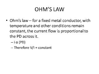
Ohm's law is the basic for studying the effect of current and voltage. Given the resistance and temperature remaining constant, the value of current is proportional to the voltage.

I = V/R  and  V= IR
......................................................


In an aircraft, the circuit does not operate independently. It can be connected to the earth.
The following are the method to be used in handling the issue of the potential different with respect to the earth.

1. Find the total resistance. It is given by the formula, Rt = R1+ R2 +R3
2. Find the current flowing in the circuit, I = V/Rt
3. With the current known, the voltage drop for each resistor can be calculate.
4. If the earth point is identified as above, the potential at each point with respect to the earth can be easily identified.

----------------------------------------------------------