I am consolidating the modules in one blog. This is done to enable easier searching by readers...
I had prepare 18 slides for the topic shared below:
MODULE
5 SLIDES
CHAPTER 12 –
ELECTROMAGNETIC ENVIRONMENT
Slide 1 - Syllabus as Per Part 66
Electromagnetic Environment Syllabus (part 66) (Level – L2)
Influence
of the following phenomena on maintenance practices for electronic system:
EMC-Electromagnetic Compatibility
EMI-Electromagnetic Interference
HIRF-High Intensity Radiated Field
Lightning/lightning protection
Slide 2 WHY THE
INCREASED CONCERN IN RECENT YEARS? BECAUSE:
- Greater dependence on electrical and electronic systems for
continued safe flight.
- Reduced electromagnetic shielding due greater use of
composite materials.
- Increased susceptibility of electrical and electronic systems
to HIRF due to increased data bus and processor operating speeds, higher
density integrated circuits and cards, and greater sensitivities of electronic
equipment;
- Expanded frequency usage, especially above 1 gigahertz (GHz);
Increased severity of the HIRF environment because of an
increase in the number and radiated power of radio frequency (RF) transmitters;
and
- Adverse effects experienced by some aircraft when exposed to
HIRF.
Slide 3. ADVERSED
EXPERIENCES
The experiences had proven the need consider the threat seriously.
Gross
navigation error in a passenger aircraft in USA (from Newark to San Maarten)
caused by a portable tv set used by a
passenger.
Lap
top used by a passenger affected the navigation equipment during aircraft
take-off and landing.
4. ELECTROMAGNETIC
ENVIRONMENT
Caused
by transmission of electrical energy in space, e.g from radar, radio or TV.
Like
current flowing in a wire, magnetic fields are created.
EMC
– Electromagnetic Compatibility
Electromagnetic compatibility, or EMC means that a device is compatible with (i.e.,
no interference is caused by its electromagnetic (EM) environment and it does not
emit levels of EM energy that cause electromagnetic interference (EMI) in other
devices in the vicinity.
All
electric devices or installations influence each other when interconnected or
close to each other. Eg your TV set, your GSM
handset, your radio and nearby washing machine or electrical power lines.
5. The
purpose of electromagnetic compatibility (EMC) is to keep all those side
effects under reasonable control
Electromagnetic
interference or EMI, also
called radio frequency interference or
RFI. It is the disturbance that affects an electrical circuit due to either
electromagnetic induction or electromagnetic radiation emitted from an
external source.
If
avionics equipments are left unprotected, may cause serious flight safety
issues.
6. EMI
SOURCES (electromagnetic
interference)
EMI
IN AIRCRAFT
SOURCES
OF EXTERNAL INTERFERENCES (note P168)
Two
forms of interference
Conducted interference
Radiated interference
Sources
of interferences
External Electrical Systems e.g brushes, switches
Engines system – ignition system
Inadequate
bonding
Faulty static discharger/wicks
7. CONTROLLING
THE INTERFERENCE
Well
Located aerials – the interference to the comm/nav systems like ADF and VHF
Electronic
equipment to be grounded and the related wires to be shielded and grounded.
The lighting current flows through the outer
skin and discharge to the extremity.
Bonding
– all equipments to be bonded together, min R = 0.05 ohms.
Static
Discharger – provide the low resistance path to the admosphere.
8. WHAT
IS HIRF
It
is High
Intensity Radiated Fields (electromagnetic
energy) external to the aircraft, of a strength sufficient
to have adverse affect on aircraft
safety.
Note:
The source of energy is external, exclude onboard system and static sources.
9. LIGHTNING
The
high energy and high voltage can affect the aircraft hardware as well as the
data.
The
high transient discharge current can damage the skin of the aircraft and the
bonding wires.
10. PROTECTION
AGAINST LIGHTNING
Aircraft
skin
Voltage
and current protector at the equipment
Wire
shielding
11 PERSONAL
ELECTRONIC DEVICES (PED)
Personal
Electronic equipments can produce signals that affect electronic equipments.
However
there was no definitive proof of individual cases. Symptoms and failures went
off when passengers were asked to switch PED.
12. The
cautions were founded as some of the sensitive electronic wires run in close
proximity to passengers.
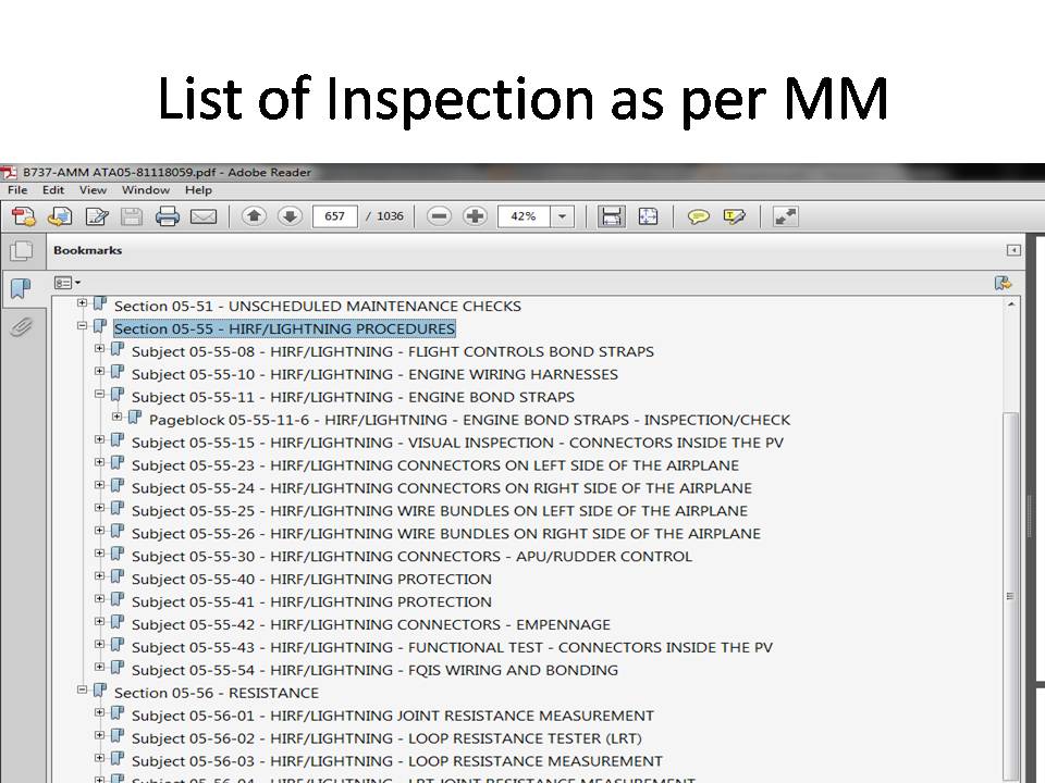
TYPICAL
INSPECTION (P166)
13 REVIEW and QUESTIONING